
Burroughs 205
Maintenance and Reliability
or
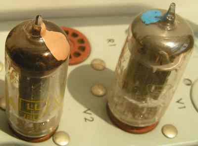
Why is there paint on the top of those tubes?
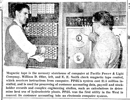
We were fortunate to have an outstanding electronics "wizard" who serviced the B205 at the University of Portland. Bill Oller was probably the only person in the world to ever take care of the health of three B205 systems. It was not unheard of to find multiple service personnel associated with a single system.
Maintenance issues forced the removal of Burroughs 205 systems at both Pepperell and Aetna Insurance in New York City.
Oller was a direct employee of Pacific Power & Light in downtown Portland. He had completed the Burroughs formal maintenance training program and knew the machine like most of us know the inside of our homes. While his primary responsibility was maintaining the PP&L system, he also took care of the University of Portland "backup" system located downtown at American Data Services. He welcomed the challenge of taking on a third system on the U of P campus in 1963 and maintained that system as well for two years.
Oller was captured in this 1960 photo in The Oregonian that featured a couple of Portland's most prominent computers in an article announcing an upcoming Business Machines Show.
This chart gives the history of the four different Datatrons that were installed
in Portland.
| Portland Datatron Installations | |||||
| Site | Approx. Serial # | Notes | Location | Install Date | Removal Date |
| Pacific Power & Light | 44 | Now in Bozeman, MT. at the American Computer Museum | 920 SW 6th. | June,1957 | 1967? |
| Oregon Centennial | 71 | Shipped to the Centennial Show after being exhibited in New York City at the World Petroleum Congress | Expo Center | June, 1959 | Sept., 1959 |
| U of Portland | 90 | Later move and installed on U of P Campus, 1965 | American Data Services in SW Portland | Mar., 1960 | 1967? |
| U of Portland | 15 or ?? | Sold to General Insurance in Seattle. Originally installed at G.I. in Jan., 1956 as a 204. Upgraded or possibly replaced at G.I. when Cardatron capability was added in early 1957. | U of P Campus | Aug., 1963 | 1965? |
Bill didn't find the General Insurance Datatron to be much of a problem compared to the system that had been installed at the Oregon Centennial in 1959. Although that system had only a paper tape reader and a Flexowriter for peripherals, it had limited air-conditioning! Here is a picture of the system in operation at the Exposition Center:
Courtesy of the Charles Babbage Institute,
University of Minnesota, Minneapolis.
Vacuum Tube Reliability
Oller and other top Burroughs maintenance staff knew that the vast majority of problems with the machine stemmed from vacuum tube failures but they actually developed a workable plan to deal with the problem. Simply put, vacuum tube failures follow a rather predictable pattern. Out of a large number of newly purchased tubes, a few will be bad to start with. A few more will suffer from filament failure in their first few hours of use. After that, the rest will function well for perhaps a few thousand hours and then failures will begin. As time passes, the failure rate increases gradually, then dramatically.
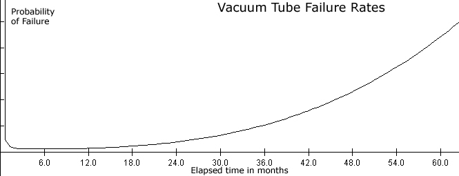
A few of the better B205 maintenance people developed a scheme of preventive maintenance to combat tube failure. Every six months, a quarter of the tubes were replaced with new units. Not all at once, of course, but on a gradual basis. Roughly once a week, Oller would shut down the computer and replace about 20 tubes in the Datatron. Each of the tubes was marked on the top with a colored dot of paint. The paint color was changed every six months. You could look at the tube tops and quickly determine which were already eighteen months to two years old and due for replacement.
The net result was that no tube in the system was more than two years old and we had a remarkably low failure rate.
Running Margins
When the computer was restarted, another preventive maintenance procedure was
performed called "running margins." The Datatron power supply was in a
cabinet of its own and supplied a myriad of different voltages to different
points in the computer and peripheral cabinets. The voltages were all regulated
and monitored on a series of twenty-two meters mounted on the Power Control
Unit.
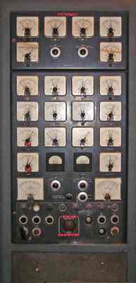
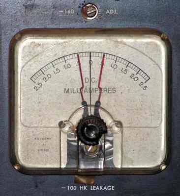
Most of the meters had red "limit needles" that were set to insure that the monitored voltage or current did not fall outside of allowable tolerances. Any variation that moved the pointer to the red needle would sound an alarm. The power supply unit was remarkable stable. In my four years I not only never heard an alarm, I never even saw a voltage out of the center of its monitored range.
Most of the power supply's voltages could be adjusted via a small flat blade screwdriver on a control mounted immediately below the corresponding meter. Several of these voltages were quite critical to the operation of the machine. "Running Margins" consisted of adjusting three of these voltages to be slightly off their normal levels, both plus and minus a few percent, and then running a diagnostic program that stressed the machine.
The morning startup sequence consisted of powering on the system followed by running margins on the three critical voltages. This took about twenty to thirty minutes after which the computer was ready for a day's work.
The combination of these procedures resulted in a very reliable system for a first-generation vacuum tube machine. We probably experienced less than one failure a month and those were usually quickly fixed. The typical repair consisted of Bill Oller coming on site, looking for a tube with an open filament and then replacing it. This might involve turning off the lights in the computer room for a few minutes to help spot the offending tube.
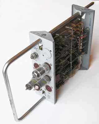
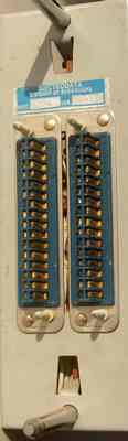
If the problem was more complex than that, Bill kept a stock of pre-tested plug-in modules nearby that could be swapped into place. The entire system consisted of these plug-in modules that were connected to the back plane via a pair of 32-pin connectors.
Really serious problems - those that didn't respond to the previously described fixes - meant getting out the logic diagrams and the Tektronix oscilloscope. A large series of two-foot by three-foot blueprint diagrams mapped out the flow of pulses throughout the computer bays. Shape and timing of various pulses were shown on the diagrams. The more complex failures usually consisted of discovering why a pulse wasn't arriving at particular point at the right time.
This type of problem solving separated the men from the boys when it came to repairing both first and second-generation computers. Bill was clearly Superman.
System Reliability
Just how reliable were these early machines? Not very, by our current
standards. The Mean Time Between Failures on the 205 Datatron was 43 hours
during September of 1957. If you were running a two or three shift
operation, that was a couple of failures each week. And that 43 hours was
only for the central system. When you added in a Card system, it would
drop below 30 hours. But for the time, those were competitive numbers and
much better than what had been experienced in the very first machines.
Burroughs tracked their own customer's numbers with considerable interest. (The
smaller E101 checked in at 29 hours.) But how did those numbers stack up
against the competition? Martin H. Weik authored
a series of studies, "A Survey of Domestic Electronic Digital Computing
Systems" for the U. S. Department of Commerce, Office of Technical
Services. When the second of these was published in June of 1957, it
listed Mean Time Between Failure (MTBF) as reported by numerous organizations
for their computers. The figures lend some insight into what the pioneers
were experiencing.
Large Scale Experimental and One of a Kind Systems
| Manufacturer | Model | Customer | MTBF |
| EDVAC | Aberdeen Proving Grounds | 8 | |
| Ferranti | Mark I | University of Manchester | 45 |
| IAS | Princeton Institute for Advanced Study | 20 | |
| ILLIAC | University of Illinois | 22 | |
| JOHNIAC | Rand Corp. | 10 | |
| MANIAC | University of California (Los Alamos, N.M.) | 5 | |
| General Electric | OARAC | Wright Air Development (USAF) | 15 |
| ORDVAC | Aberdeen Proving Grounds | 6 | |
| Raytheon | RAYDAC | U. S. Navy (Point Mugu) | 0.33 |
| SEAC | National Bureau of Standards | 3 | |
| Burroughs | UDEC | Wayne State, Detroit | 7 |
| Whirlwind I | MIT | 19.4 |
Large Scale Commercially Manufactured Systems
| Manufacturer | Model | Customer | MTBF |
| IBM | 701 | AEC, University of California | 6.2 |
| IBM | 701 | Lockheed Aircraft | 4 |
| IBM | 701 | Lockheed Aircraft | 1.5 |
| IBM | 702 | Bank of AMerica | 2 |
| IBM | 704 | Lockheed Aircraft | 4 |
| IBM | 704 | Lockheed Aircraft | 4 |
| IBM | 704 | University of California | 17.9 |
| IBM | 705 | Farmers Insurance | 8 |
| Sperry Rand | Univac I | University of California | 5.5 |
| Sperry Rand | Univac 1103A | Ramo-Wooldridge | 10 |
| Bendix | G-15 | Michigan State Highway Dept. | 80 |
| Bendix | D-12 | Griffis Air Force Base | 40 |
| Alwac | III E | David Taylor Model Basin | 43 |
| Underwood | Elecom 50 | Underwood, New York City | 6 |
| Underwood | Elecom 120 | Shell Development | 10 |
| IBM | 650 | Ames Aeronautical Lab. | 36 |
| IBM | 650 | Chrysler Engineering | 32 |
| IBM | 650 | Chrysler Engineering | 60 |
| IBM | 650 | Cook Research | 40 |
| J. B. Rea | Readix | Wright Field | 36 |
Duncan MacDonald drew three conclusions from this data:
- Reliability of the early institutional systems is very poor, as is that of
the early IBM 700 series.
- The IBM 650 and the 205 Datatron are apparently equally reliable.
- E101 reliability is comparatively very low for its small size.